





Showing posts with label wheelchair repair. Show all posts

Thursday, 31 May 2018

User Repair -No. 2


User Repair - Number 2 (When necessity drives action)

Having finished a day's work outside in the yard, I entered the quiet of my home.  Click...click...click...click,,,  What the heck is that?  I get off the Quantum 6000 powerchair I am currently using and examine the lower right chassis from where the sounds seems to emanate.  There between the right tire and chassis I see a dangling spring --- one end connected, one end not.  Something is broken.

Checking the mirror-image left side, I see that the front of the spring on that side is attached to the pivot-point on the rear of the caster arm.  (Think of it as the elbow which bends up and down allowing your caster to bounce up or down over obstacles.)  The back of the same spring appears to be attached to a rod-like structure which drops down (from where?) and the bottom has a loop through which a tensioning-bolt protrudes.

It appears that by tightening the nut on the tensioning bolt, you can add or release pressure on the spring.  But for what purpose?  The front attachment point of the spring is fixed (doesn't move).  I cannot get down to floor-level to better examine the rod through which the tensioning bolt protrudes so I can't tell what it is attached to or if/how much it moves.  I would think it would have to move back and forth - otherwise why would a spring be necessary?  (if two fixed points there would be no need for the spring any more than driving two nails into a board and stretching a spring between them --- to what purpose?)  I cannot physically reach the rear attachment point to tug on it to see if it moves.  My wife was commandeered for the task which left me no further informed.

I downloaded a Quantum 6000 manual and though they have a couple of 'exploded' diagrams, none show the spring assembly in question.  Short of my jacking the wheelchair up from the floor and removing the tire, I cannot determine the function of this spring/tensioning assembly.

Repair Shop

So I unhook the dangling broken spring and remove the bolt from the rear attachment point.  It is obvious that one hook-loop has broken off of the spring.  I take the parts and head down to the only wheelchair repair shop in the city,  I show the parts to the receptionist who disappears into the bowels of the service department.  After a short while she re-emerges to tell me that all the field-service technicians are out on appointments but that a parts-person said they do not have that item in stock.  I was told I could make an appointment for a house call or one to bring the chair in for servicing. 

"How long is your waiting-list for appointments I ask"  for the last time I needed service (see broken caster-bearing replacement),  I was told two-weeks.  That was unacceptable!  Well, it the situation has not much improved.  The only other wheelchair repair franchise (Shopper's Home Healthcare) divested themselves of powerchair sales and service.  Now my service provider has acquired many of their clients, yet qualified wheelchair technicians remain in short supply.

The question is "what is the function of this tensioning-assembly and will I damage anything by driving without it" as the powerchair seems to drive as before the assembly broke.  I'm given no answers.

The Repair

So I go back to my home shop and root around to find a spring of somewhat the same size and tensile strength.  I find one but it is about an inch too long.  Below is my home-made replacement for the assembly in question.


The above photo shows the non-broken spring (left side).  It is difficult to see as it is tucked in behind the caster arm (to which it is attached) and is stretched to a second attachment point further back.  It is the small gray spring between the larger yellow spring and the tire.


A closer view:  Here you can see that the front hook of the spring goes through a hole in the clip which is attached to the pivot-point at the rear of the front caster arm.


Here is the rear attachment point for the back end of the spring.  It is quite difficult to see as it is hidden in the shadows.  (using a flash did not help as the bouncing light bleached out the photo.  The solution would be to drop a light in between the tire and chassis - something I was unprepared to do.)  The inset photo in the upper-right is somewhat clearer.


This photo shows the original right broken tensioning spring assembly.  Both ends of the spring should have the final turn made into a hoop.  As shown, only one hook is remains (at top of photo).  The second hook previously went through the hole in the bolt.  The bolt was then pushed through a hole on the rear attachment point (an arm with a hole in the bottom) A locking nut (pozi-lock or similar was threaded onto the opposite end of the bolt and tightened to apply tension to the spring.


Tools:  Because my replacement spring was about an inch too long I had to shorten it.  To do this, I took the temper out of the spring by heating it with a torch then letting it cool slowly.  When cool, I clamped it in a vice and used a hacksaw to cut the desired length from the spring.  The freshly cut end was then twisted outwards forming the hook. A file cleaned up sharp ends.  The spring was re-heated then dropped in cold water to once again temper the metal.  (I have no degree in metallurgy but this seemed to do the trick.)  The tensile (?) tension strength of the spring seemed about equal to the broken one when completed.  Totally unscientific!  Hope the tempering did not make the metal too brittle.  Aside: my shop is still a work in progress - this is my improvised shop on the top of a bucket.


Broken original on left (1) bolt with hole in one end and nut threaded on the other and (2) the spring with broken end-loop.  On the right is (3) the replacement spring I created and (4) the section of spring I cut off.


So here is my newly fashioned spring.  (1) is the locking nut which tightens against the rear arm attachment point (2) is the bolt with a hole through which hook of the spring is inserted.  (3) is the spring itself and (4) is the spring hook which attaches to the rear of the front caster arm.  The nut travels up or down the bolt to apply the required tension. (arrows)

Theoretically you would hook the front hook (4) through the hole on the rear of the front caster, then stretch the spring and push the bolt through the hole in the rear attachment arm.  Once through you would thread the nut onto the bolt and tighten appropriately. (whatever that is)

I said "theoretically" as in practice my wife helper and I found that my spring (as did the original one) have so much tension that it probably could not be stretched by any one person and would require mechanical assistance.  The bolt was only about a quarter of an inch too short to reach the rear mounting arm hole where the nut and ratchet nut driver would do the work stretching.  Technicians must have some sort of jig to do this work for them,  I have no way of knowing what tension had to be applied or if it is critical.  As both the original spring and my newly made spring seemed to exhibit identical strong tension (elasticity), I simply tried to match the size of spaces between coils of the original spring (left side) to my replacement spring (right side)

My solution was to replace the bolt (2) with an eye-bolt that had a longer shaft.  With the bolt shaft through the rear mounting arm hole, the nut was tightened with the ratchet driver.  Sorry, I failed to take a photo of this but it was an eye-bolt similar to the one below.


The hook end of the spring now went through the eye of the bolt.  The extra quarter-inch made the difference and it seems to be holding just fine.

Of course, once finished I find myself in our neighbourhood auto/mechanical parts store and find the perfect spring replacement in both size and tension.  Still there are no open hooks on either end but could be easily modified with a hacksaw or other metal-cutting tool. (arrows)


I wonder what the parts and labour would have cost at my service provider had they been available?

Ah, what desperation will drive one to do!

*   *   *

Wednesday, 17 September 2014

Permobil Arm Problems -Continued


From the preceding posts you've seen the shortcomings of my Permobil M-300 wheelchair.  This is a chair that is just about 2 years old and is used almost exclusively indoors.  At this point, I would gladly trade back to my 7 year old Quantum if able.

When I was first shown the Permobil M-300 by the salesperson, I raised my concerns about the very flimsy side arms.  The side to side play seemed quite excessive and I was concerned about using them for transferring.  The salesperson assured me that they would stand up to repeated transfers but promised to swap these arms out for a new model "which would be available in about three months time".  In fact I remember the phrase he used "they would be rock-solid!".  In recent conversations with a shop technician, I was told that the Permobil M-300 has only two arm styles, both were available at the time of my purchase and the alternative is less stable that the one I currently have.  I was lied to in order to have me commit to the sale!!


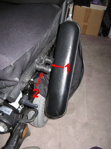
Shown here is the Permobil M-300 forward arm post which should drop into the hole shown by the red arrow. While this photo shows about 3/4 of an inch separation between the center of the post and the center of the locking mechanism (hole), the side to side play is even greater. In fact the post and arm can completely miss the mechanisms and the arm would spin around 360 degrees if not stopped by the floor as shown below.


Here, the Permobil M-300 arm post has completely missed the latching mechanism 1 and has hit the floor.  The arm swings equally backwards hitting the floor behind the chair.  The stop mechanism which should restrict the arms movement backwards (when raised) is ineffective!  By holding onto the arm and transferring to the chair, the stress flexes the bolts attaching the mechanism and eventually the bolt(s) snap.  While easy enough to replace, this mechanism is poorly designed by Permobil's engineers and the user should not be repeatedly placed in the position of having to replace the bolt, or for those less capable, or to have a wheelchair repair technician dispatched to do the same, for a price, of course.  I was able to obtain comparable bolts from a local hardware supply (Home Depot) however, they had about the same tensile strength and also sheared (snapped) after repeated transfers.  Perhaps a titanium bolt from a specialty company would survive longer however the proper solution would be for the Permobil engineers to redesign the post and capture system.
Also shown in the photo are the two round or tubular spacers 2, one of which was lost in transit when the bolt last snapped.  The rear arm attachment point is greatly responsible for this side to side play and overall weakness of the arm.  I had attempted to improve the rear hinge assembly by adding an aftermarket (Home Depot) oversized metal washer (for stiffness) and a rubber washer (for friction/resistance).


Shown here is the side arms overly complicated rear hinge attachment mechanisms with my exterior (aftermarket) oversized siffening wash and behind it the rubber washer (arrows) which adds some resistance thereby dampening the dropping motion if the arm is released.  I believe the silver coloured lever seen on top of the photo is suppose to be used to adjust the tension or resistance of the arm's motion -so it won't drop too fast.  I said "I believe" this is its purpose as this has never been effective in dampening the drop and perhaps over tightening the lever cause the mechanism to snap.  Unfortunately, Permobil chose to use some sort of plastic resin to manufacture this item which is itself slippery by nature and offered little resistance and being plastic, is very fragile and will break when stressed.

 As I mentioned, the last time the locking mechanism's bolt broke, I was in transit and the broken bolt fell out taking the tubular spacer with it, all lost!  As the arm, was about to drop off and as I still had some days to work, I took the entire broken arm assembly off of the wheelchair to prevent further damage.  (that is, I had no arm on the left side of the wheelchair) In doing so, I found what I refer to as the plastic tensioning spacer, broken into three sections - as they tumbled out to the floor.


This is a photo of what I refer to as Permobil tensioning spacer, shown here broken into three sections.  The item is made from some sort of fragile plastic resin and has no internal strengthening structure such as fiberglass or carbon fiber which might give it some three-dimensional strength.  Better yet, I could be made of aluminum or some other metal and if too slippery, be coated with some resistive material to add tension.  No glue would hold this together so it would have to be replaced.


In the above photo, the transfer arm can be seen extending above the 'M300'.  Attached directly to the frame, this is suppose to be stronger or more rigid than using the side arms for transfer.  At the time of purchase, the salesperson assured me the arms were strong enough for transfers, as they were found on the wheelchair.  Inset is the previous photo showing the location of the broken arm tensioning spacer.  A 3/4 inch (outside diameter) tubular metal spacer with a central hole for the 5/16th diameter bolt that holds the arm to the chassis, ran through the curved portion of the plastic spacer.

So here is what happened:  I call up my wheelchair service provider, Shopper's Home Healthcare -Bartley Drive Unit, and have the Permobil wheelchair picked up for servicing - I get an old loaner in return.

(The Permobil wheelchair was at the Shopper's Home Healthcare, Bartley Drive Shop for about two months before being returned to me.  Much more on that in an upcoming post.)
 
I have the chair returned after two months and find the broken bolt and lost spacer replaced.
They also attached a 'Transfer Bar' so that I could transfer using this rather than the fragile side arms.  This would have been fine with me if it had been discussed with me beforehand - am I agreeable?, will it help me?, what will it cost me?, etc.  Two months, really??!!

So below is a very short video clip of what the repair job accomplished.


Basically, this is how the chair was returned to me after two months in the shop.

As you can see, the side to side play is still very extensive.  Raising the arm, I found that the three broken pieces of the arm tensioning spacer that I had sent back to the shop with all the other parts of the broken side arm were simply placed back into the mechanism.  A new part was not installed - broken parts were reinstalled!  While I now use the transfer bar to transfer, it is all but impossible not to lean into the arms when reaching or simply when relaxing.  Repeated regular pressure will eventually snap the bolts regardless.  In the end, after two months in their repair shop,  side to side play or movement is just as extensive as before the Permobil wheelchair was sent in for repairs and my same broken part was replaced.  At least I wasn't charged for this "service" nor for the installed transfer bar which I was not informed about nor agreed upon.  One bonus was that my motor cover was removed but not replaced!

Below is my solution to this poorly designed and engineered  sidearm hinge.


I removed all the plastic segments of the broken arm tensioning spacer and replaced them with large metal washers (2 inch outside diameter with 13/16th hole). I reused the central hub which was previously enclosed by the plastic arm tensioning spacer.  The bolt (3&1/2 inch in length, 5/16th diameter, #18 Posi-lok nut) (nylon thread resists loosening).  All parts obtained from the local hardware store (Home Depot).  Tightening the nut seen on the outside of the unit, passing through the hub (not seen) and washers added whatever tension I wanted and would hold the arm in whatever position I wanted.  If I find it too stiff, I plan to get one of those thin cutting sheets available in any 'Dollar Store' or kitchen supply store.  I find they are made of a thin, somewhat slippery, plastic which is cuttable.  Use the metal washer for a template and cut plastic washer to insert between the metal ones to produce a smoother action.  I have found this to be unnecessary at the present time.

If I wish, in the future I can get a block of aluminum from a metal supply company and machine my own fancier version, but for now, this works and performance is all I wanted.  The arm has very little side to side play.  It is stiff side to side but moves smoothly when raised up and down.  There is enough tension that the are will stay raised wherever I might place it.  It will not slam down either front or back.

Sadly, this is what passes for service these days....
I will have much more to say about this in upcoming posts.


*   *   *